steveeasy
Well-known member
Just fitting a new control panal, well starting and got confussed trying to work out why I’ve got supply from both 1 and 2 for the existing switch Panels.
I was sure I should only have a supply from one of those the other being purely for the battery.
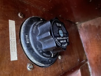
It seams not to be the case. On 1 I have domestic and engine and on 2 I have domestic and the engine. Is this correct ?. Looks incorrect to me.
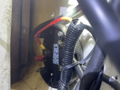
I’ve an engine battery and domestic battery with the N terminals connected heading off to the engine. Then a positive coming back to the 1 2 b switch. See image. The positive from starter motor is at the bottom of 1 2 B switch. Where the domestic supply is taken from.
makes no sense to me!!
Steveeasy
I was sure I should only have a supply from one of those the other being purely for the battery.
It seams not to be the case. On 1 I have domestic and engine and on 2 I have domestic and the engine. Is this correct ?. Looks incorrect to me.
I’ve an engine battery and domestic battery with the N terminals connected heading off to the engine. Then a positive coming back to the 1 2 b switch. See image. The positive from starter motor is at the bottom of 1 2 B switch. Where the domestic supply is taken from.
makes no sense to me!!
Steveeasy
.jpg")

