Eberspacher 701 timer wiring.

Gone sailing

Well-Known Member
Joined
28 Oct 2013
Messages
94
Location
Langstone
Visit site
I have a eber d3l and a 701 timer. It is the cheaper ex BT type with no diagnostics.
I have wired it in but the thermostat does not seem to adjust the temperature as the heat keeps coming even when the temp is turned down low!
I now think that I may have it wired wrong.

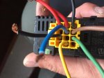
On the wiring loom from the eber there is a yellow, red, brown, blue, green, and two black wires.

On the wiring to the timer I have a yellow, red, brown and grey with red stripe.

I guess I match the colours yellow, red and brown but where does the grey with red strip go? Is this the thermo?

I've looked through some wiring diagrams and other resources online but none of my colours seem to match what they state so your help would be appreciated.

Thanks
Jim
 
the timers grey/red is the 'heat control lead'.
I don't recognise all your loom wires, red is+ive and yellow the trigger wire to fire up the system, brown is -ive but I don't know abut green and the blacks.
If you cant sort it let me know and I will 'delve further' in my old manuals.
 
Is a d3l compatible with a 701??? I though the 701 was for Airtronic heaters only????? May be wrong. (It has happened before, check with SWMBO)
 
Hi thanks for your help.
See the attached pictures, one is the old terminal that I cut off the other is the wiring diagram. They seem to suggest that a6 and a9 are the temp setting wires so that would be brown and green. but I only have one wire for temp setting on the controller? Maybe it is not compatible!?
Jim
 

Attachments

  • image.jpg
    image.jpg
    82.7 KB · Views: 7
Last edited:
The D3L is an analogue control system and the 701 control head is designed for the Airtronic digital heaters so it is probably not compatible. It's a long time since I have had any dealings with Ebers but I recall the thermostat used for pre Airtronics was an actual thermostat switch rather than a potentiometer which sets the target temp via the ECU, the part number for that is 25 1557 80 01 00
 
egarding the picture of the cut off connector. This looks like the 12 pin connector for the 7 day timer with diagnostics ( forgot the model name) If so that wiring is not standard.
Red and yellow are correct. The green which is in a6 should be slate and red and,as you say is one of the temp control wires.
The wire to a9 should be brown/white and is the other temp control
The blue should be blue/white and is the diagnostic control a8
a4 ( black in yours should be brown (-ive) and should be looped over to a12
the red wires which correctly go to a10 and a11 indicate that the timer is rigged to run for 24 hours.
Why change the ( very handy) ‘diagnostic timer’ for the less useful ‘van timer’?
Does this help?
If your heater ran with the diagnostic timer it should run with the ‘van’ (701) timer
 
Hi, yes it is the connector for a 7 day timer, unfortunately it stopped working the lights came on but no screen info.
The 701 timer was in the box when I bought it off ebay.

So which of the two temp control wires are you suggesting I should connect? a6 or a9(or both) I guess a6 is the same colour as on the 701 wiring. Can I damage the ecu buy trying each one? Trial and error?

Are you also saying that the two black wires should be joined together and connected to negative?
I currently have the brown (a9) from the main loom connected to brown on the 701 loom.
 
To clarify
From the 701 loom.
Red connects to a7 and a8
Yellow connects to a2
Brown connects to ? A4 and a9?
Grey with red strip connects to ?
 
Sorry, I am having to write off line and then past into the forum site.
i am a bit confused about your reffering to the old connector connection numbers, I thought that we would just dispense with them and connect to the 701 using the leads from the heater.
The red from the heater goes to red on the 701 yellow from heater to yellow 701 brown from heater to brown 701.
The odd one out is your green from the heater which seems to be equivalent to red/slate and should be connected to red/slate from the 701.
Any clearer?
 
Top