Depolarized Alternator of VP 2030

Chanquete

Well-Known Member
Joined
18 Jan 2013
Messages
202
Location
Buenos Aires, Argentina
Visit site
Hello!
I would very much appreciate advices about this problem
My VP2030 starts immediately and runs softly.
Suddenly the non charging alarm sounds.
Tester measurements on the alternator output indicate no charging.
The alternator was dismantled showing that all components were OK.
The mechanic said that "he polarized the alternator" and subsequent bench measurements showed that the alternator was performing very well, charging without problems.
Anybody has an idea about what could have happened in the engine for depolarizing the alternator?
Where to look in order to avoid another depolarization?

Thanks in advance!
 
What a stramge stateement the mechanic made re "polarising"
he may be living in the long ago when a generator relied ona residual magnetism to get it to start generating power to provide its own field magnetism through the field coil.
It was possible then to polarise the residual magnetism in the opposite direction to give a negative output rather thna positive output or visa versa.
Alternators do not hold significant residual magnetism so rely on current from the battery often via the charge light to provide enough magnetism in the filed coil to gnerate voltage to then provide its own voltage for the field coil. (via the regulator).
I can only suggest that if he did check the laternator function is OK then you have a wiring problem in the boat. (not uncommon). good luck olewill
 
On Large alternators polarity can be reversed if current is fed into it in the wrong direction. This should be protected against by the reverse power circuitry but this can fail and I have seen electricians jump start the polarity back to the correct direction with a battery. Incidentally in such occasions the alternator will jump about on its mounts as if it were mechanically unbalanced. I have never seen it happen on small alternators as fitted to yacht or car engines? If your alternator is not producing a current it is far more likely that the diode pack (rectifier) has blown. This can happen by surges through the circuitry from a number of sources including shore power, welding, lightening etc etc. The rectifier can often be changed and just unscrews off the back of the alternator. Some alternators may require a complete replacement. I am not sure if yours is fixable or not?
 
Hello!
I would very much appreciate advices about this problem
My VP2030 starts immediately and runs softly.
Suddenly the non charging alarm sounds.
Tester measurements on the alternator output indicate no charging.
The alternator was dismantled showing that all components were OK.
The mechanic said that "he polarized the alternator" and subsequent bench measurements showed that the alternator was performing very well, charging without problems.
Anybody has an idea about what could have happened in the engine for depolarizing the alternator?
Where to look in order to avoid another depolarization?

Thanks in advance!

Like William and Cryan i do not understand what your mechanic is telling you. Alternators, unlike old fashioned dynamos, do not generally retain any magnetism. Dynamos did and it was essential for their operation.

It is possible that if the warning light has blown or if there is a bad connection between it and the alternator that it will not be getting the current it needs for the initial excitation and will therefore not start to generate although it would do if this current is supplied independently of the warning light circuit. This would sort of agree with what the mechanic is saying.

Does your no-charge warning light come on at all?

Check out the warning light circuit and if no joy take the alternator to an automobile electrician. They will be able to test it and should be able to repair it.

In light of what your mechanic has said my money would be on a problem with the warning light circuit I think.
 
On the 2030 the warning light does not supply the excitation current. There is a resistor for the purpose. It could have failed.
 
Is that located in the alternator or in the Vovo penta panel?

In the panel. I'll have a look for a diagram.

CORRECTION sorry it's on the engine, between D+/61 on the alternator and pin 3 in the multi way connector, in a blue/red wire.
It's energised whenever the panel is turned on.
Circuit diagrams in the operating manual on the VP website.
 
Last edited:
In the panel. I'll have a look for a diagram.

CORRECTION sorry it's on the engine, between D+/61 on the alternator and pin 3 in the multi way connector, in a blue/red wire.
It's energised whenever the panel is turned on.
Circuit diagrams in the operating manual on the VP website.

Troubadour: I thank you very much for taking your time analyzing the VP Manual wiring diagrams just for helping!.
Its a privilege for Forum visitors to benefit with your contributions.
Now I think we have detected the dubious wire and next saturday, in our clubs mooring we will follow it to find the failing contact problem.

I also thank the suggestions of other forum contributours.

Chanquete
 
On the 2030 the warning light does not supply the excitation current. There is a resistor for the purpose. It could have failed.

In the panel. I'll have a look for a diagram.

CORRECTION sorry it's on the engine, between D+/61 on the alternator and pin 3 in the multi way connector, in a blue/red wire.
It's energised whenever the panel is turned on.
Circuit diagrams in the operating manual on the VP website.

No problem, I have a 2020 and am familiar with the circuit. Good luck.


I think the existence of an "excitation resistance" may depend on the version

Not used on the A series ITWF find but used on the "B" series and later.

The OP does not say which version he has!

Did this coincide with a change from incandescent bulbs to LEDs in the panels ?
 
On Large alternators polarity can be reversed if current is fed into it in the wrong direction. This should be protected against by the reverse power circuitry but this can fail and I have seen electricians jump start the polarity back to the correct direction with a battery. Incidentally in such occasions the alternator will jump about on its mounts as if it were mechanically unbalanced. I have never seen it happen on small alternators as fitted to yacht or car engines?

What is this all about? Are others too shy to ask? The output polarity of an alternator is dictated by the diodes and their connections. Voltage alternating from +ve to -ve comes out of the actual alternator before the rectifiers. In the case of a true alternator giving AC then polarity is not a question.
If the DC supply to the field coils of any alternator are revered then it will still provide AC with no concern except the Ac will be out of phase. not a concern un;less there are 2 alternators paralleled. So what is Cryan referring too? olewill
 
Did this coincide with a change from incandescent bulbs to LEDs in the panels ?

No, still a bulb.

Yes I see what you mean about the change.
Looking at the control panel circuit, it appears to coincide with the change of warning module from a crude bare board layout that gives confusing indications, the cct of which is shown in the type A manual, to a sealed unit that works better (until it fails which is not too uncommon and they are well over £100 :(
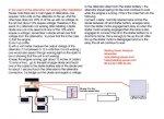
). The bulbs are the same. The later version manuals don't show the cct of this unit, just a black box.
However the sealed unit is backward compatible. I fitted one to an old 2002 in place of the bare board type. I haven't checked if that has the excitation resistor, probably not.
Maybe the resistor is a backup in case the bulb fails?
Or maybe it passes more current than the bulb? Do the bigger alternators common now need a bit more excitation to get started? I don't know the resistance value, can't be too low or it would stop the bulb lighting. I think the bulbs are 1.2W, normal instrument sort of rating.

Apologies if I have misled the OP - which engine version do you have?

Edit - just found my spare bulbs, they are 2W.
 
Last edited:
Do you have a split charge diode ?

Where to look in order to avoid another depolarization?

I had similar problems partly caused by a faulty negative wire from the alternator to the main earth on the engine block and partly by the Sterling Splitter Diode, the answer was on the Sterling website part detail below :-
 

Attachments

  • Sterling Split Charge 2.jpg
    Sterling Split Charge 2.jpg
    99.6 KB · Views: 0
Troubadour: I thank you very much for taking your time analyzing the VP Manual wiring diagrams just for helping!.
Its a privilege for Forum visitors to benefit with your contributions.
Now I think we have detected the dubious wire and next saturday, in our clubs mooring we will follow it to find the failing contact problem.

I also thank the suggestions of other forum contributours.

Chanquete


Finally the alternator revivied!
The failure was the lack of initial current in the auxiliary field winding connected to D.
Some words about the electriciab concept of repolarizing. He simply connected a small light bulb 9W 12V between +B and D the excitation winding. This current was sufficient for the alternator to begin performing well.
Once the alternator was running the bulb turned off because the voltage difference between +B an D became zero.
The exciter resistance was broken, we replaced it 33 ohm, 9W.
Just in case, as a spare part I will take onboard the small lightbulb with two crocodile terminals.

I thank all the valuable advices!
 
Glad you got it fixed.
Your electrician did not "repolarize" the alternator, he simply supplied the start-up excitation current that was missing. Once it's running it does not need this.
Does your charge failure warning light on your instrument panel operate?
 
Glad you got it fixed.
Your electrician did not "repolarize" the alternator, he simply supplied the start-up excitation current that was missing. Once it's running it does not need this.
Does your charge failure warning light on your instrument panel operate?

Hello Troubadour

Its exactly what you wrote, the excitation current was missing.
I have not noted if my charge failure warning lamp on my instrument panel operates. The usual luminosity of the sky and the sun at our latitud (34 ºS) makes difficult to note the warning light.
But my instrument panel also has a voltmeter.
When the alternator was not working the no charge alarm was ringing and the voltmeter indicating 12 V instead of 13.5V or so.

Do you suggest that the warning light bulb could operate as a excitation resistor? Perhaps should I test this light?
 
Do you suggest that the warning light bulb could operate as a excitation resistor?

Certainly on older engines, yes it should. As Vic pointed out they do not have the resistor.
I don't know whether the resistor is there as a backup in case of bulb failure, or whether the bulb does not supply enough current for larger modern alternators.
I suspect it is just a backup.
Was your failed resistor marked as 33 ohms? I'm surprised it is so low. That might make your warning light bulb quite dim (although you might be able to see it in the ambient light here :()

About the resistor; On board we have looked at the wiring diagram of original manual that came with the engine.
There you can find the excitation resistor printed with 33 ohm 9W.
In on line workshop manuals, the value of this resistor (under point 9) is not indicated.
My electrician excited the alternators field with a small bulb 12V only 3W pointing +B with D.
After hours we started the engine again with the alternator functioning 100%

Maybe its a good idea to inspect the charging light at the instrument panel.
I am a little confused about replacing this bulb at the panel.
Is it an easy procedure?
In my boat I have access of the instrument panel by the rear, inside the boat.
 
Top