DC Engine Wiring

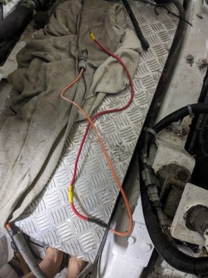
Mystery solved regarding the the 135a connection.. I was being a bit of a banana!! It's not an input it's an output!!.. It's the output from the alternator. .. The alternator cables run to the 135a breaker and then the heavy red cable travels a few miles to the house battery connection..
Good job I checked as now I have separated the house batteries from the starter battery, the way the two engines were configured they both would be charging the house batteries and nothing the starter battery..

I'll give myself a bit of a 'wally award' for that one :D
 
A thought about the orange wire on the starter, could go to a relay for glow plugs/stop solenoid etc, the relay being energised by thinner wires from the helm switches.
There's an intermediary starter relay before the starter solenoid mid way along the engine. I think.. (Think being the operative word) the orange cable may run to the starter relay.. (magnetic switch as CAT call it)
 
Hi guys... Mystery solved. Firstly thanks for all your help. I now have a much better picture as to how the engine electrics have been played with..
I'll attach another couple of pics. Firstly the stbd engine alternator output wire has had a very creative bodge done to extend it to the battery. That cable is being ditched and something resembling the OEM cable on the other engine will be used to charge the starter battery..

Secondly the solenoid wires... The medium orange cable going from the solenoid (on the same pole as the power input) is the live feed for the intake heaters. The red wire, which I'll attach a pic of, at some point in its life was an orange wire and now is a 'Blue Peter' wire of a number of pieces (also to go in the bin!). That wire from the same pole is to the starter relay (magnetic switch) input and the output of the relay runs to the 4th terminal on the solenoid at the bottom, which is the actuator terminal..

Cracked it in the end!! Thanks guys..
 

Attachments

  • alternatoroutputbodge.jpg
    alternatoroutputbodge.jpg
    91.1 KB · Views: 6
  • startersolenoidpowercable.jpg
    startersolenoidpowercable.jpg
    89.1 KB · Views: 4
Hi guys... Mystery solved. Firstly thanks for all your help. I now have a much better picture as to how the engine electrics have been played with..
I'll attach another couple of pics. Firstly the stbd engine alternator output wire has had a very creative bodge done to extend it to the battery. That cable is being ditched and something resembling the OEM cable on the other engine will be used to charge the starter battery..

Secondly the solenoid wires... The medium orange cable going from the solenoid (on the same pole as the power input) is the live feed for the intake heaters. The red wire, which I'll attach a pic of, at some point in its life was an orange wire and now is a 'Blue Peter' wire of a number of pieces (also to go in the bin!). That wire from the same pole is to the starter relay (magnetic switch) input and the output of the relay runs to the 4th terminal on the solenoid at the bottom, which is the actuator terminal..

Cracked it in the end!! Thanks guys..
Well done so far, but.... the alternators are wired wrong, they should not go straight to the batteries, else the alternators are always live.

1) You can connect one alternator to the engine batteries by simply connecting it to the main battery cable on one starter, that way it's isolated when you turn the engine isolator off. Connect the other one to the load terminal of the domestic isolator. Never turn the isolators off with the engine running. Downside with this method is that the engine battery charges very quickly and after that you don't get the benefit of that alternator also charging the domestic batteries.

One way to overcome this is to fit a voltage sensitive relay (VSR) between the two battery banks, which only closes when one or the other bank is being charged, staying open and keeping the two banks separate when no charging is taking place.

Another option would be to fit a Victron Argofet to the alternator that's charging the engine battery, so it charges both banks. Downside to that is if that alternator fails you don't have any engine battery charging, but that equally applies to method 1 above. Solution to that is to fit an Argofet to each alternator. The Argofet outputs can be connected in parallel, so only one par of wires to run back to the isolators, where you make the connections to the load terminals of the isolators.
Thanks Paul. Good thinking. Funnily enough that relates to the original problem which was when all the power was switched off I was finding the alternator was still live, which I certainly don't want.

I'll look into these options.. :cool:
 
Thanks Paul. Good thinking. Funnily enough that relates to the original problem which was when all the power was switched off I was finding the alternator was still live, which I certainly don't want.

I'll look into these options.. :cool:
Here's a basic VSR schematic, having 2 engines makes no real difference here. You could connect each alternator to it's main battery cable on the starter solenoid, then fit the VSR next to the batteries or the isolators, whichever is more convenient.

Charging-2-banks-VSR.png

Here's the basic layout for Argofets with twin engines. Negatives are not shown for simplicity, but each Argofet has a 2.5mm negative connection.


Charging 2 banks from 2 engines with Argofet.jpg
 
Here's a basic VSR schematic, having 2 engines makes no real difference here. You could connect each alternator to it's main battery cable on the starter solenoid, then fit the VSR next to the batteries or the isolators, whichever is more convenient.

View attachment 200031

Here's the basic layout for Argofets with twin engines. Negatives are not shown for simplicity, but each Argofet has a 2.5mm negative connection.


View attachment 200032
Thanks Paul. I'll have a study of this. I notice a number of people including some professionals still advocate a direct connection from the alternator to the battery so long as it's fused. Obviously that's not an angle you take with this I see. :cool:
 
Thanks Paul. I'll have a study of this. I notice a number of people including some professionals still advocate a direct connection from the alternator to the battery so long as it's fused. Obviously that's not an angle you take with this I see. :cool:
That would work on a car where the single alternator charges a single start battery but on a boat you usually have more than one charge source, alternator, shore power, solar, generator and more than one battery bank, eg starter, house, bow thruster, windlass.

Something more bespoke is called for to manage the circuits (protection and isolation) as well as proper charging, float and monitoring of battery states.

On our mass produced Beneteau Oceanis, the Yanmar engine is supplied on a pallet to the boat builder with a fat wire connecting the alternator to the back of the starter motor with the intention that the starter battery is simply connected to that. Beneteau cut that wire (and lazily leave it in situ) then run new cables from alternator to the VSR/ACR and from start battery isolator back to the starter etc.
 
Thanks Paul. Good thinking. Funnily enough that relates to the original problem which was when all the power was switched off I was finding the alternator was still live, which I certainly don't want.

I'll look into these options.. :cool:
It isn't the end of the World if the alternators are connected directly to the batteries, as long as they are fused at the battery, but i can't think of any benefit in doing so, other than if someone turns the main isolators off with the engine running it doesn't harm the alternator diodes.

For you setup i think i'd go with a VSR, rated for the combined alternator outputs. All you need to do then is connect each alternator to it's main battery cable at the starter solenoid, so the charge current goes back to the batteries via those main cables. When the isolator is off everything is off. Fit the VSR wherever it's most convenient. I'd recommend a Victron Cyrix.
Thanks Paul. Very much appreciated. I'll look into this..
 
That would work on a car where the single alternator charges a single start battery but on a boat you usually have more than one charge source, alternator, shore power, solar, generator and more than one battery bank, eg starter, house, bow thruster, windlass.

Something more bespoke is called for to manage the circuits (protection and isolation) as well as proper charging, float and monitoring of battery states.

On our mass produced Beneteau Oceanis, the Yanmar engine is supplied on a pallet to the boat builder with a fat wire connecting the alternator to the back of the starter motor with the intention that the starter battery is simply connected to that. Beneteau cut that wire (and lazily leave it in situ) then run new cables from alternator to the VSR/ACR and from start battery isolator back to the starter etc.
Thanks mate.. Your guidance has made things a lot clearer. Much appreciated.
 
Top