Checking VHF aerial and cable .

clyst

Well-known member
Joined
18 Aug 2002
Messages
3,233
Visit site
Hi guys ...... im having a bit of a problem with the radio with very broken transmission and reception . Iv tried another radio but problem still exist . It now seems the problem is with the aerial or cable . Is there any easy way to check it without climbing the mast or using an SWR meter . The 9nly gear I have at hand is a common voltmeter . Regards Terry
 

Plum

Well-known member
Joined
6 Jun 2001
Messages
4,534
Location
UK East Coast
Visit site
Hi guys ...... im having a bit of a problem with the radio with very broken transmission and reception . Iv tried another radio but problem still exist . It now seems the problem is with the aerial or cable . Is there any easy way to check it without climbing the mast or using an SWR meter . The 9nly gear I have at hand is a common voltmeter . Regards Terry
Have you tried removing/isolating all your onboard usb chargers? Some are known to affect VHFs, particularly on receive, so worth eliminating.

Www.solocoastalsailing.co.uk
 

srm

Well-known member
Joined
16 May 2004
Messages
3,248
Location
Azores, Terceira.
Visit site
Buy a new antenna with sufficient cable already fitted. Test the radio with this. Even if you do get the existing antenna to work you will have a spare for emergency use.
Also, some AIS sets have an antenna test function, if yours has (or you can borrow one) exchange the cables and run the system test routine.
 

Martin_J

Well-known member
Joined
19 Apr 2006
Messages
4,405
Location
Portsmouth, UK
Visit site
Best way really is the use of a Power/SWR meter at each point in the feed (or as SRM says, use the inbuilt functionality within an AIS transmitter)..

Not sure if you've used an SWR meter before but my videos in this previous post shows how quick the tests can be..

SWR Meter

If you're in the Portsmouth area just say and you can try it out.
 

clyst

Well-known member
Joined
18 Aug 2002
Messages
3,233
Visit site
Many thanks for all who offered a loan of an swr meter ( takes me back a bit to my sad to say CB days 😄) but before I get too involved and the fact that I have an internal mast conn I will check there first ( forgot there was a join as its above the headling ) Failing that I can disconnect the ASI aerial and conn direct into VHF . Thank guys for giving me an arse kick to put ideas in place ......which I should have thought about myself 👍👍
 

KompetentKrew

Well-known member
Joined
27 May 2018
Messages
2,438
Visit site
I said:
I've been thinking about this quite a bit recently, as I want to test my own aerial, and surely an SWR meter doesn't tell you how the antenna operates under load?

I think it's correct to say that you can make a simple dipole with two bits of wire, cut them to the right length, and you'll get a perfect score with the SWR meter. Is that right?

So I would expect the SWR meter to always show a perfect score as long as there's a circuit to the VHF aerial, there's no short circuits and the aerial itself remains the right length.

I would expect the most common failure mode of boats' VHF antenna systems to be corrosion, the cable affected by salty air, high in humidity. Here's a pic the 25-year-old coax connector on my boat, but this is just a pic of the outside and I have no idea what the conductor / shield is like on the inside.

Presumably coax is specified with a certain cross-section of conductor to carry a given transmission wattage (you'd need a thicker coax if you were operating some big high wattage AM broadcasting transmitter for the World Service, for example), so at some point corrosion in the ends of the cables &/or the coaxial connectors can reduce the effective cross-sectional area of the cable to below that required by the transmission wattage. As the wattage increases, so does the effect of any resistance caused by corrosion?

I'd guess an SWR meter or NanoVNA will only send a low wattage down the cable - milliwatts? It's testing whether the antenna is the right length for the transmission frequency, isn't it? So it's quite possible that it will show a good result even though corrosion in the cable or connectors has degraded it to the point at which it can't properly carry the 5W or 20W signal that your VHF transmits. The coax will carry the low wattage of the SWR meter, but not the higher wattage of actual transmissions?

I recently found this video which shows how to test coax with a wattmeter and dummy load, and this approach seems to me likely to be more suitable. However it's not equipment that most of us will have lying around.

I'm only a foundation-grade dork, so I apologise for any errors I've made. I'm posting these thoughts for constructive criticism.

Ignore this comment completely, I'm a muppet.
 
Last edited:

howardclark

Active member
Joined
16 Sep 2001
Messages
383
Location
S. Wales
Visit site
I believe my meter tells me exactly what the situation is under load! It sits in the middle when you transmit. Like many others mine can be borrowed- I’m based in Dartmouth
 

Martin_J

Well-known member
Joined
19 Apr 2006
Messages
4,405
Location
Portsmouth, UK
Visit site
Kompetent Crew... The meter doesn't send the carrier... that's done by whatever transmitter you connect to it's input.

My videos in that thread I linked to just now only showed a lower power but I could have put 100W carrier through it just as easily from the Icom I have on board although for a quick and portable test the handheld is better than nothing.

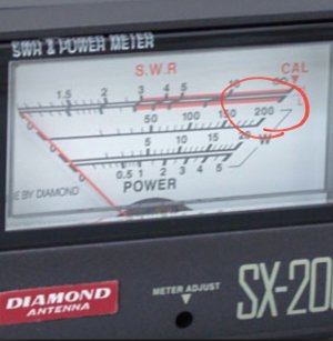
A fairly common meter will cope with 200W forward power..

Screenshot_20230408-160323_Samsung Internet.jpg


If you find a lot of reflection at low power then we can assume there will be a lot of reflection at higher power... Any bad joints preventing higher power I would expect to be measurable at the lower power test.
 

KompetentKrew

Well-known member
Joined
27 May 2018
Messages
2,438
Visit site
Thank you to you both, and my apologies for being a muppet. I was assuming an SWR meter worked the same as a NanoVNA.
 

James_Calvert

Well-known member
Joined
6 Oct 2001
Messages
2,536
Visit site
When I was having aerial problems, I bought an emergency one that clamped to the pulpit. Used that for the rest of the season until replacing the defective one. Convinced it was the above deck connection which was the problem. Since then I've always routed the aerial cable all the way from the mast to the set with no connections. Means I have to withdraw it when the mast comes down for rerigging, but I'm happy with that.
 
  • Like
Reactions: srm

Alfie168

Well-known member
Joined
28 May 2007
Messages
58,744
Visit site
I can lower the mast relatively easily on my boat and I have recently run a new VHF cable and put a new terminal on the top end and bought a new aerial. My problem is I'm not convinced the soldered pin on the cable end projects far enough into the aerial. I don't want to re-erect the mast if it's not a good connection. I don't want to pull it apart again if it's OK either. The cable is a continuous run through a deck gland and unconnected to anything as yet.

How do I test it ? Keep it simple please. I only have a basic multimeter..or three, which I'm thinking is not enough from my run through this thread.🙄
 

srm

Well-known member
Joined
16 May 2004
Messages
3,248
Location
Azores, Terceira.
Visit site
I have recently run a new VHF cable and put a new terminal on the top end
This is a bit too late for you now, but may help others.
Having messed around with VHF cable connections out in the open when I lived in an area where masts were taken down whenever a boat was ashore for the winter (due to high winds) I now only buy antenna factory fitted with sufficient length of cable to reach from the masthead to the chart table and VHF/AIS in one uninterrupted run. No matter how carefully I made and encapsulated the connection the working life was invariably only a couple of seasons.
 
Top