Battery Monitor

Ian_Rob

Well-Known Member
Joined
31 Jan 2008
Messages
1,209
Visit site
I think it would be easier to work this out on the boat but I am not able to get down for another month.

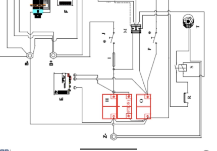
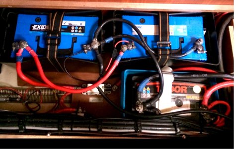
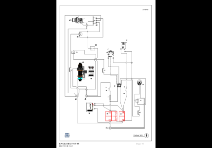
In the meantime, based on the attached circuit diagram and photograph, I wonder if it is possible for anyone to advise how I should go about connecting a Victron BMV 712 Smart Battery Monitor to the system.

I only want to monitor the 2 x Domestic Batteries. Thank you.
 

Attachments

  • IMG_0683.png
    IMG_0683.png
    1.4 MB · Views: 55
  • IMG_0686.jpeg
    IMG_0686.jpeg
    349.6 KB · Views: 48
  • IMG_0687.png
    IMG_0687.png
    256.4 KB · Views: 42
Last edited:
Positive cables can be left as they are. You need top rearrange the negatives. I would suggest that you fit a negative busbar and connect the negatives as in the diagram below.

Charging-2-banks-VSR.png
 
Last edited:
What @PaulRainbow said. I notice you have a smaller black wire going to the clamp on one of your house negative terminals - this needs to be moved to a busbar so it doesn't bypass the shunt. I am commenting just for clarity, nothing should be connected between the shunt and the batteries or the shunt will not work correctly.
 
I need to digest the comments and Paul’s diagram but thanks very much for your posts. The small black wire is the negative supply from the solar panels.
 
I need to digest the comments and Paul’s diagram but thanks very much for your posts. The small black wire is the negative supply from the solar panels.
You can ignore everything in my schematic except the black wires. Your solar wire also goes to the busbar,
 
Just to follow on from this, a quick question. The existing battery cables are 50mm2 with M10 ring terminals. Is it acceptable practice to go with a busbar with M8 posts or will the larger ring terminals tend to work loose? Reputable ones with M10 posts seem pricey!
 
Top