TradewindSailor
Well-Known Member
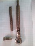
I've often wondered how well a roller swage fitting integrates with the wire.
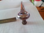
I thought you might be interested in these photos of the eye terminal (top) of a 3 yr old shroud.
Points:
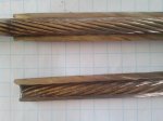
The wire is 12mm
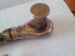
The hole is (16.5mm) stretched to 17mm toward the end. Standard 12mm eye terminals are 19 mm diameter.
The crack? In the end of the terminal .... Impossible to see whilst rigged due to the toggle
The roller swage was one pass rather than using a second pass to roll out the shoulders as is this riggers usual practice. You can see that the swaging process was complete with good forming of the swage.
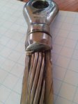
Despite this terminal being the top terminal, dirt has penetrated 30 mm into the swage. If this was a lower terminal it could be more. This would support the crevice corrosion cause of failure for these fittings in general. ( This fitting is 3 years old).
The fitting is slightly bananaed .... but not enough to worry me
One strand of the 316 1 x 19 wire was broken at the internal shoulder of the swage entrance. This could be due to accentricity during swaging. Broken strands like this are much more visible when the wire is loaded ... The tend to contract back into the fitting when not.
Any thoughts?
I thought you might be interested in these photos of the eye terminal (top) of a 3 yr old shroud.
Points:
The wire is 12mm
The hole is (16.5mm) stretched to 17mm toward the end. Standard 12mm eye terminals are 19 mm diameter.
The crack? In the end of the terminal .... Impossible to see whilst rigged due to the toggle
The roller swage was one pass rather than using a second pass to roll out the shoulders as is this riggers usual practice. You can see that the swaging process was complete with good forming of the swage.
Despite this terminal being the top terminal, dirt has penetrated 30 mm into the swage. If this was a lower terminal it could be more. This would support the crevice corrosion cause of failure for these fittings in general. ( This fitting is 3 years old).
The fitting is slightly bananaed .... but not enough to worry me
One strand of the 316 1 x 19 wire was broken at the internal shoulder of the swage entrance. This could be due to accentricity during swaging. Broken strands like this are much more visible when the wire is loaded ... The tend to contract back into the fitting when not.
Any thoughts?