Alternator booster wire

Dull Spark

Well-Known Member
Joined
31 Aug 2017
Messages
103
Visit site
My alternator has an extra booster wire connected to an old Driftgate XAlt booster system. It feeds a Driftgate XSplit system and does a very good job of keeping my 1x110Ah and 2x110Ah banks charged. Following a previous query, some of you were kind enough to point me at manuals for the system. (Driftgate is no longer trading.)

I've sorted out one or two problems caused by broken or loose connections, one episode of which drove the voltage at the battery terminals to almost 17v for a few minutes.

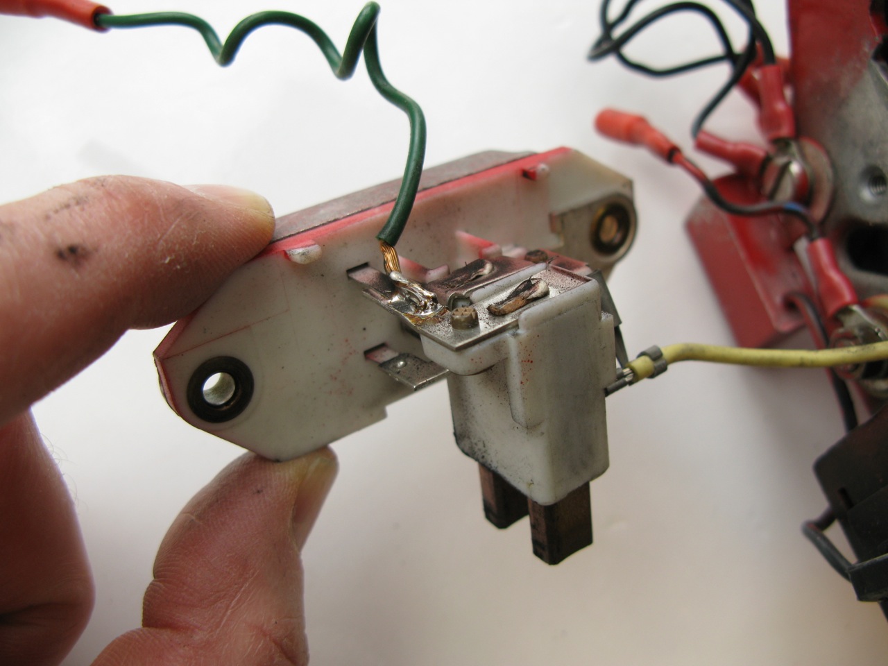
The alternator is an Iskra 100A and I reckon it has the booster wire connected between the internal regulator and the negative brush. (I think it is connected to the output of the regulator, DF. If I'm right, the alternator field without this extra wire would be generated by the voltage difference between output D+ and DF. With the extra wire, the voltage difference generating the field is somehow increased to give extra alternator output. I can't see a way to increase D+ , so the only way I can see to increase this voltage difference is to reduce the output DF to the negative brush. This could be by shorting it to earth via the extra wire (probably in fast pulses rather than constantly)

All good stuff to ponder on, but I really haven't a clue. Can anyone tell me how the extra wire works its magic?

(I understand the technology used is MOSFET, which gives "ultra low loss diodes" with volt drops of 0.1v rather than about 0.6v which might otherwise be expected)
 
Can anyone tell me how the extra wire works its magic?

I doubt there is any magic in the wire, is it not just a connection between the field coil and the external regulator (X-alt)?
My understanding is that the regulator is connected in series, either on the positive or the negative side of the field coil. In the case where an external regulator is used while the internal regulator is still in place, I guess the deciding factor will be where the internal regulator is connected. At least that is how it is done with my external regulator, Adverc, which comes in a negative and positive version.
I also have an Iskra alternator (65A), not sure if it is any help, but the photo below shows how the field coil connection to the Adverc is soldered to one of the brushes (the negative IIRC).
regulator.jpg

But perhaps your question is more how voltage regulation works in detail?
 
The X-Alt works by feeding current in a programmed manner to the alternator field coil, via the brush. This gives a higher voltage than the built in alternator regulator. It has a voltage sensing connection to the battery IIRC and is not intended to be adjustable, if the alternator is producing ~14.8v in its boost phase then it's working properly.
The X-Split has really an entirely separate function and provides electrical separation between the battery banks so one doesn't discharge into the other(s).
The low-loss design allows the batteries to see the full alternator output voltage, unlike some other devices.
 
Last edited:
Many thanks for your advice and an excellent photo. I'm just trying to understand how it works. As I understand it, there is a voltage D+ fed from the three diodes (diode trio?) into the internal regulator and to the positive brush. The negative brush is fed with DF from the internal regulator output, so the voltage across the rotating field is the difference between the two. So how does the extra wire increase this voltage difference. Does it increase D+ or decrease DF or both? And if so, how does it do it?

On a more practical level, my experience is that loss of battery "sense" drives the alternator output to fairly high voltages. Just the usual broken wires or bad connections. I assume that when that happens, the only thing that holds down the alternator voltage is the batteries themselves.
Many thanks.
 
I put a similar Adverc system onto a small sailing boat over winter and was surprised on how much better the 2 batteries charged. It involved stripping the alternator but was definitely a very good addition to a small boat with very little power generation in comparison to a bigger boat.
 
The negative brush is fed with DF from the internal regulator output, so the voltage across the rotating field is the difference between the two. So how does the extra wire increase this voltage difference. Does it increase D+ or decrease DF or both? And if so, how does it do it?

I am not sure that "voltage difference" across the field coil is the best approach to understand alternator regulation.
My view is that the regulator constantly monitors/measures output voltage between D+ (the yellow wire in my photo) and ground (the alternator case, by way of the attachment bolts). What the regulator does is allowing a certain amount of current to flow through the field coil in order to maintain the output voltage.
Regulation of current flow through the coil is achieved by very rapidly switching on and off, therefor voltage may not be a very meaningful figure.
As mentioned, the extra wire is just there to enable an external regulator to override the internal regulator.
 
After perusal of Superheat's #5 Dropbox, I realise how simplistic was my question. Clearly, much to read and digest. Many thanks to all for your advice. I will have to join the digital world and not simply think of voltage as BabaYaga advises!
 
Top