OceanSprint
Well-Known Member
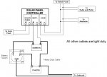
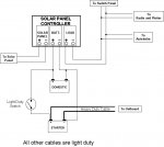
I have attached 2 circuit diagrams - as they are now, and how I plan to change them.
Now: It is almost two separate circuits. The solar panel charges the domestic battery, which drives everything on the boat. The starter battery is connected direct to the outboard, and is charged by it when it is running. There is a link through a light cable and very light duty switch. Hence when this switch is closed the starter battery could act as a backup to the domestic battery, but the domestic could not help the starter battery start the engine as the cable link is too light - with a risk of a fire?
Future: I think my proposed set up will work. With the new battery switch set to "2" it is the same set up as now - with two separate circuits - the starter battery starts the outboard, and is charged by it. The solar panel in this setting still charges the domestic, which is still connected to the switch panel etc. Everything connected to the domestic battery has it's own local switch. But now with the battery switch on "1", the domestic can start the outboard, and when set to "both" the batteries are in parallel.
Can anyone see a snag with my proposed new set up?
Thanks
Bill