Adding one "house" battery. Circuit ok? Kit upgrades needed?!

SScrapper

New Member
Joined
11 Jan 2020
Messages
10
Location
Hants
Visit site
Hi all
Just joined, first post - forgive the newbie question...! Have recently taken over my father's boat a 45yr old Trapper 28 - which I have known most of it's life and learned to sail yachts on in my early teens.
Am going through her bit by bit... Electrics is the one thing over the years I've not really done too much on.... So...
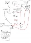
Rough diagram attached - hopefully it's readable! Seems to me like a simple set-up. I think it has been in place like this for at least 20 years.

i'm adding add a second house battery (House 2) as shown (not connected up). Same Hankook 75Ah, deep cycle.
Q1) does the network and connectivity look a appropriate set-up?

I'm planning to link H1 to H2 in parallel IE -ve to -ve and +ve to +ve. And attach end of cable A onto the +ve terminal of H2 rather than H1 where it currently is.
Q2) would this be the right approach?! I'm thinking so the charge from the alternator will do both H1 and H2 (hopefully) evenly ?

The Batt mgmt is Adverc (can't see any model/desc on it). The isolator is Surepower model 702 (max Alt amps 70 - so presumably the alt doesn't do any more than that!)
Q3) do I need to upgrade the Adverc and/or the Isolator?
Q4) Is the Alternator up to the job? (Mostly weekending and occasional week-2 week trips)

And just to confirm... !
Q5) When starting engine, I should have only the Sw2 closed (on)? and then also close Sw1 when the engine runs to charge the house batteries as well?

Apologies for what are probably basic questions, but before I seek professional help - personal and electrical! - I thought I'd ask.
Any and all feedback and comments very gratefully received!
Cheers
 

Attachments

Welcome

Sort of OK , assuming the Adverc is all correctly wired
( Adverc installation and wiring diagram at https://7688827d-8948-4a64-a325-c18...d/adc29e_47244e3309044b28bc355309d3fa8e3b.pdf )

Your proposed method of connection of the 2nd house battery is correct .

The Surepower 702 is a diode splitter, It will charge both the engine start battery and the house batteries simultaneously regardless of the position of SW1 and SW2
You can close both switches before starting the engine if you wish.
SW2 must be closed to start the engine and I'd expect to leave it closed while the engine is running to power the engine control panel and instruments

Some concern about the "thin red" wires from the alternator to the Surepower diode splitter and onwards to the two switches. Not too thin I hope. They must be thick enough to carry the full alternator output current safely and without excessive volts drop ... Id expect them to be something like 8.5 or 10 mm²

I note you have no fixed provision to start the engine from the house battery . Jump leads are a possibility but you must be aware of the hazards.... I'd opt for an emergency linking switch

You do not show any fuses

I hope what you show a "bus bar" is in fact separate + and - busbars and will not short out the whole lot as your diagram suggests .

Cannot say if the alternator is up to the job without knowing its max output rating and your electrical power needs but unless you have loads of electrical equipment using a lot of power I expect it is

The diode splitter must be rated at no less than the alternator max output

The Adverc senses the volts being delivered to the house bank and controls the alternator to compensate for the volts drop across the diode splitter.

What engine do you have ?
 
Last edited:
i'm adding add a second house battery (House 2) as shown (not connected up). Same Hankook 75Ah, deep cycle.
Q1) does the network and connectivity look a appropriate set-up?

I'm planning to link H1 to H2 in parallel IE -ve to -ve and +ve to +ve. And attach end of cable A onto the +ve terminal of H2 rather than H1 where it currently is.
Q2) would this be the right approach?! I'm thinking so the charge from the alternator will do both H1 and H2 (hopefully) evenly ?

Cable A goes to H2, as does the cable to SW1

The Batt mgmt is Adverc (can't see any model/desc on it). The isolator is Surepower model 702 (max Alt amps 70 - so presumably the alt doesn't do any more than that!)
Q3) do I need to upgrade the Adverc and/or the Isolator?
Q4) Is the Alternator up to the job? (Mostly weekending and occasional week-2 week trips)

No alternator details, but it's more than likely up to the job.

And just to confirm... !
Q5) When starting engine, I should have only the Sw2 closed (on)? and then also close Sw1 when the engine runs to charge the house batteries as well?

Makes no difference, you may as well turn them both on. The Surepower diode will charge both banks whatever the switch combination.

VicS suggestion of an emergency switch is a good one. All you need to do is make the cable from H2 to SW1 the same size as the cable from the engine battery to SW2, then add a 3rd switch, connected to the load terminals of SW1 and SW2, again using the same cable as from the engine battery.

Oh, welcome to the forums (y)
 
Hi all

I'm planning to link H1 to H2 in parallel IE -ve to -ve and +ve to +ve. And attach end of cable A onto the +ve terminal of H2 rather than H1 where it currently is.
Q2) would this be the right approach?! I'm thinking so the charge from the alternator will do both H1 and H2 (hopefully) evenly ?

Welcome

Your proposed method of connection of the 2nd house battery is correct .

I have just reread your post and my reply.

To clarify
Connect the two batteries in parallel ( positive to positive and negative to negative )
and
Make the negative connections to the pair ( wire to starter battery neg and wire to neg bus bar) to one battery and the positive connections ( red wire "A" to Adverc and red wire to SW1 ) to the other battery.
 
Id also suggest connecting the outputs from the diode splitter to the switched sides of SW1 and SW2

Suggested revisions shown in red on the attached diagram
 

Attachments

  • SScrapper wiring.jpg
    SScrapper wiring.jpg
    86.8 KB · Views: 27
VicS, PaulR - thank you both very much. That's v helpful.

You are correct ref the busbar, and noted ref the lack of fuses - they are there, just ont on the diag :)

- I'll check the size of cabling, but the 'thinnness' was relative to the batt terminal cables.
- "connecting the outputs from the diode splitter to the switched sides of SW1 and SW2" - I have a feeling that may just have been my misrepresentation on the diagram, but will check!
- "Switched" side = "Load" side?
- Engine is a 2 cylinder Lombardini Marine LDW602M - 611cc, 15.8hp, 3600rpm wide open throttle (so I'm told!). Prob about 25 years old and runs very nicely.
I presume the Alt doesn't push out >70 amps because the diode states its max is 70 amps and it's been like that for years!

Thanks again !
Malcolm
 
Switched side = load side ? .... Yes

70 amps is the smallest of the Sure Power diode splitters
I think the alternator will be 33 amps or 45 amps if original
 
Hi Vics - just checked the connections from diode to the switches and they are not currently attached to the switched sides of SW1 and SW2 - my diag was correct representation.
Is there a problem / any disadvantage leaving them as is? (I won't be putting in the emergency switch quite yet)
Many thanks

If you connect to the battery side of the switches ;
Turning the switches off with the engine running will not harm the alternator.
If there is a short in the charging wiring, turning the switches off will not isolate that wiring.
If there is a fault that requires one battery to be isolated, charging still goes to the faulty battery.

If you connect to the Load side of the switches ;
Turning the switches off with the engine running will likely harm the alternator.
If there is a short in the charging wiring, turning the switches off will isolate that wiring.
If there is a fault that requires one battery to be isolated, charging will not go to the faulty battery.
 
Thanks Paul :) So on balance, as long as neither switch is turned off when the engine is running, it's better to have the diode connected to the load side. Makes sense.
Presumably with this set up, the start batter is not utilised / drained (once engine is off) by interior demand - only the the house batts are...
Many thanks!

Yep, correct on both points.
 
Top