ProDave
Well-known member
I have am old Lowrance chartplotter that had been having intermittent communications issues with the GPS receiver then by the end of last season had become a permanent loss of communication.
This is a plotter that has what I call a "GPS receiver" and many call a GPS puck. It is a round thing on the coach roof that contains an antenna and GPS receiver and communicates that to the plotter over a dedicated NMEA cable. Taking the plotter home and opening up the plotter (as the only accessible point to make measurements) confirmed there was no NMEA data being sent from the GPS receiver.
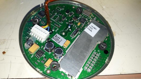
There are several version if this but ours is a LGC-12W. first issue, it seems impossible to open the unit, and nobody on the internet had found a way to open it. Well I did. The lid is glued on. To open it, you go around the visible joint with a sharp knife then start tapping at the joint with a chisel slowly working your way around and eventually you will break the glued seal and the lid will come off. Inside is a tin can and inside that is a circuit board. Here is a picture. Not much chance of making a repair to that.

So a replacement was needed. To buy the correct thing was about £80. If I had to pay that much I would rather put it towards a new plotter.
So the search was on for a cheaper alternative, and indeed there are many cheap GPS receivers / pucks to choose from.
I chose a NEO-6M GPS receiver module, and ordered one on ebay from China for the grand sum of £3.28. This link gives a good description of what the module does, stop reading when you get to the discussion about connecting it to an Arduino. In-Depth: Interface ublox NEO-6M GPS Module with Arduino
I chose this bare board option as I wanted to build it into the existing housing of the old failed one and hence continue using the cabling and connectors from the old one buried in the headlining of the boat.
The only immediate issue was the new one defaults to 9600 baud, but the plotter defaults to 4800 baud.
A month later it arrived and I connected it. I only connected power, ground, and TX (from the GPS) to RX (at the plotter)
I set the menu on the plotter to 9600 baud and turned it on. Nothing. I thought perhaps the adjustable baud rate only applied to the comms port on the plotter not the dedicated GPS port, so I set the comms port to "NMEA GPS INPUT" and 9600 baud and fitted a jumper wire in the plotter to connect my incoming signal to the comms port RX. Again nothing.
Some more head scratching and probing around with my oscilloscope, and i concluded the logic polarity of the NMEA signal from this GPS receiver was wrong. So I knocked up an inverter with a transistor, and now I had a working GPS signal into my plotter.
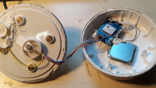
So i have tidied it all up. Mounted the receiver and it's aerial into the lid of the the original receiver

And then glued the lid back on.
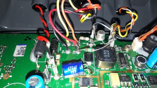
Inside the plotter, I made my logic inverter a little tidier

And that is it. A working GPS signal again for total cost of £3.28 and outwardly nothing has changed, all the original cables and connectors are still in use and the receiver on the coach roof looks just like it always did.
I have to say the inverted logic thing with this particular GPS receiver is something I had not expected. And for that reason this is probably not the best choice of GPS receiver, there are others that are known to work without this inverted logic issue which might be better for most people.
This is a plotter that has what I call a "GPS receiver" and many call a GPS puck. It is a round thing on the coach roof that contains an antenna and GPS receiver and communicates that to the plotter over a dedicated NMEA cable. Taking the plotter home and opening up the plotter (as the only accessible point to make measurements) confirmed there was no NMEA data being sent from the GPS receiver.
There are several version if this but ours is a LGC-12W. first issue, it seems impossible to open the unit, and nobody on the internet had found a way to open it. Well I did. The lid is glued on. To open it, you go around the visible joint with a sharp knife then start tapping at the joint with a chisel slowly working your way around and eventually you will break the glued seal and the lid will come off. Inside is a tin can and inside that is a circuit board. Here is a picture. Not much chance of making a repair to that.

So a replacement was needed. To buy the correct thing was about £80. If I had to pay that much I would rather put it towards a new plotter.
So the search was on for a cheaper alternative, and indeed there are many cheap GPS receivers / pucks to choose from.
I chose a NEO-6M GPS receiver module, and ordered one on ebay from China for the grand sum of £3.28. This link gives a good description of what the module does, stop reading when you get to the discussion about connecting it to an Arduino. In-Depth: Interface ublox NEO-6M GPS Module with Arduino
I chose this bare board option as I wanted to build it into the existing housing of the old failed one and hence continue using the cabling and connectors from the old one buried in the headlining of the boat.
The only immediate issue was the new one defaults to 9600 baud, but the plotter defaults to 4800 baud.
A month later it arrived and I connected it. I only connected power, ground, and TX (from the GPS) to RX (at the plotter)
I set the menu on the plotter to 9600 baud and turned it on. Nothing. I thought perhaps the adjustable baud rate only applied to the comms port on the plotter not the dedicated GPS port, so I set the comms port to "NMEA GPS INPUT" and 9600 baud and fitted a jumper wire in the plotter to connect my incoming signal to the comms port RX. Again nothing.
Some more head scratching and probing around with my oscilloscope, and i concluded the logic polarity of the NMEA signal from this GPS receiver was wrong. So I knocked up an inverter with a transistor, and now I had a working GPS signal into my plotter.
So i have tidied it all up. Mounted the receiver and it's aerial into the lid of the the original receiver

And then glued the lid back on.
Inside the plotter, I made my logic inverter a little tidier

And that is it. A working GPS signal again for total cost of £3.28 and outwardly nothing has changed, all the original cables and connectors are still in use and the receiver on the coach roof looks just like it always did.
I have to say the inverted logic thing with this particular GPS receiver is something I had not expected. And for that reason this is probably not the best choice of GPS receiver, there are others that are known to work without this inverted logic issue which might be better for most people.
Last edited:
