80's Sea Ray Inboard to Outboard Conversion.

  • Thread starter Thread starter dpb
  • Start date Start date

dpb

Well-Known Member
Joined
14 Feb 2007
Messages
1,239
Location
Poole, Dorset
Visit site
First off this is not a how to post, infact it may turn out to be a how not to post as the work is under way.
The work is being carried out on my project boat, subject of this thread:

My 80's Sea Ray 197 Monaco Project

The reason for the conversion is as a result of problems with the engine restore related on this thread:

Mercruiser 4.3 V6 rebuild fail.....so next step?

To fix the engine issues was going to cost me in the region of £2000 and I still had a seized up leg to sort out and the boat is unlikely to be worth such further expediture.
At first I considered a change to an outboard of equivalent power to the existing inboard but the cost of a decent engine and appropiatley engineered mounting arrangement would be equally if not more unviable.

Eventually an idea came together based on:
A slow boat, call it a river or lake launch , would be a useable boat.
The existing bathing platform is solidly built and can take at least three adults moving around on it with out moving. (say at least 250kg)
An outboard of 15 to 25hp should achieve 10knots.
Such an outboard weighs 40 to 75kg
A decent 4 stroke 15 to 25hp can be got for about £1500
Breaking and selling the existing engine is likely to achieve at least that amount.

Simply bolting the outboard to an L bracket fixed to the top of the bathing platform was not going to work as it would be too high, even for a long shaft.
The top of the outboard mounting had to be a few inches below the top of the platform.

20241203_135459.resized.jpg

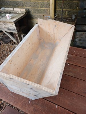
The basic design then is to build a 'box' that hangs from under the bathing platform so that the mounting point for the outboard is in line with the rear of the platform.
The section of the platform that is aft of the existing cut out will be removed to accomodate the motor head.
Construction to be from 18mm ply and GRP.

The ply is screwed together using resin as a glue.
Wedge pieces smooth the corners and a filler made from resin with added granules fills any gaps before laying up the fiberglass

20241203_135522.resized.jpg

The bottom half of the box was glassed up first before fitting the base of the outboard well. The box overall depth is determined by the need to have something to fix the lower outboard fixing bolts to which is why there is going to be a hatch for access.

20241206_112751.resized.jpg

The ply is all 18mm that was recycled from some shelving that I made years ago.
double thickness for the outboard to be mounted to.
It is probably standard ply which should not matter if my glassing is done properly. Plus the boat will be trailer stored.
All faces and edges of wood have been 'painted' with resin before assembly.
The timber pieces are pressure treated.
I have placed a couple of off cuts of ply in a bucket of water to see what happens. (nothing yet after 2 weeks)

Thats it so far.
My intention is to probably paint the box with waterproof paint for good measure, mainly as I have no idea how to apply gel coat, plus I am not sure how waterproof the lay up is without a gel coat.
The existing hole in the transome will be blanked off with resined and painted 12mm marine ply, the idea being to be able to convert back if required in the future.
Any comments welcome!
 

Attachments

  • 20241203_135522.resized.jpg
    20241203_135522.resized.jpg
    596.9 KB · Views: 1
First if you think you need marine ply for blocking the whole then you need it for your box , second, I don’t understand is the hole for the engine to go through. Also get a two stroke lighter and faster .
 
Seems fine to me. Bit heath rob but ok

Seastoke, the hole you can see is not for the engine to go through. It's for an access hatch to the lower mounting bolts for the outboard - all explained in post #1.

Gelcoat is easy so don't let it put you off. For a finished coat, mix in catalyst + styrene wax and it can be applied like a thick paint.
 
Seastoke, the intended use of marine ply on the transom is partly because I happen to have some, but also because I won't be sheathing it in GRP, though it will be either painted resined before bolting in place. If the whole thing works out then I may improve the arrangement at a later date.
The hole is as per JFM's comment.
Given that this will be a slow boat I dont think any speed advantage of the 2 stroke will be of much use and I think the quiteness of a 4 stroke will be a more pleasant experience at 8 to 10kn.

JFM, it is a bit heath rob, and is a development in progress which may need adapting or changing after trials. The two main questions for me are:
How will the boat be effected by loosing the 'ballast' of the existing engine? (Net loss of about 200kg)
I know the existing platform will take the engine but will be interesting to see how it handles the thrust of the engine.
I shall look further into the Gelcoat as always assumed it needed moulds etc....
Cheers
 
The next step of this project was to cover the ply outboard well. Whilst messy this went ok as I had got plenty of practice doing the inside of the rest of the boat.
This is how it looked:
20241206_112758.resized.jpg20241220_124605.resized.jpg

I then, on the advice / encouragement from JFM, learned about and procured the materials to apply the gelcoat which to my surprise turned out to be easier than the laying up of the mat.
I used regular gelcoat for the first coat and then overcoated that with a coat of flow coat (regular gel coat plus wax) about two hours later.
All painted on with a 3in paint brush.
Had to do the inside first, then flip it to do the rest.
The results were remarkable and are visible in later photos. So thanks JFM.

After fitting the hatch and the outboard well drain it was time to prepare the boat.

The hole for the outdrive is blanked off with 12mm ply that has been coated with resin, using 6mm bolts passing through the holes for the outdrive bolts.

20250203_143650.resized.jpg

Then the fixings between the boat and the platform were changed from a mixture of 4mm bolts and screws to 8mm bolts
The only ones I cant change are the ones at the bottom of the struts as if I were to drill through the hull at the present locations I swould not be able to acces the other side as they would be within the flotation boxes in the boat. I may add something at a later date.

Then I cut out the section of the platform using a hand saw.

20250203_150120.resized.jpg

Fixed some brackets to the outboard well

20250204_144548.resized.jpg

(Note the gelcoated finish!)

And then bolted the well to the platform.20250206_151209.resized.jpg20250206_151216.resized.jpg20250206_151227.resized.jpg20250206_151237.resized.jpg

And thats it.
Still need to tidy the mastic and improve the interface between the platform and the hull.
I can bounce on the well and it feels solid with the boat and I weigh almost twice what the outboard will.
It is ready for the engine so I am sourcing one at present.
I have decided to go 25hp fourstroke after much deliberation, even though I believe a 15hp would be fine for what I want it to do.
However with a 25hp it should be a relaxing and relativeley quite experience.
Looking forward to a sea trial soon!!!
 
Don't know as I have not bought it yet.
Some do, but at present I have no preference. The well will allow a fair bit of trim movement if not a complete raise.
 
The next step of this project was to cover the ply outboard well. Whilst messy this went ok as I had got plenty of practice doing the inside of the rest of the boat.
This is how it looked:
View attachment 189172View attachment 189173

I then, on the advice / encouragement from JFM, learned about and procured the materials to apply the gelcoat which to my surprise turned out to be easier than the laying up of the mat.
I used regular gelcoat for the first coat and then overcoated that with a coat of flow coat (regular gel coat plus wax) about two hours later.
All painted on with a 3in paint brush.
Had to do the inside first, then flip it to do the rest.
The results were remarkable and are visible in later photos. So thanks JFM.

After fitting the hatch and the outboard well drain it was time to prepare the boat.

The hole for the outdrive is blanked off with 12mm ply that has been coated with resin, using 6mm bolts passing through the holes for the outdrive bolts.

View attachment 189174

Then the fixings between the boat and the platform were changed from a mixture of 4mm bolts and screws to 8mm bolts
The only ones I cant change are the ones at the bottom of the struts as if I were to drill through the hull at the present locations I swould not be able to acces the other side as they would be within the flotation boxes in the boat. I may add something at a later date.

Then I cut out the section of the platform using a hand saw.

View attachment 189176

Fixed some brackets to the outboard well

View attachment 189177

(Note the gelcoated finish!)

And then bolted the well to the platform.View attachment 189178View attachment 189179View attachment 189180View attachment 189181

And thats it.
Still need to tidy the mastic and improve the interface between the platform and the hull.
I can bounce on the well and it feels solid with the boat and I weigh almost twice what the outboard will.
It is ready for the engine so I am sourcing one at present.
I have decided to go 25hp fourstroke after much deliberation, even though I believe a 15hp would be fine for what I want it to do.
However with a 25hp it should be a relaxing and relativeley quite experience.
Looking forward to a sea trial soon!!!
Well done.

If you wanted to refine the fixing a little, after satisfactory testing, these would look neat (painted white) ;
 

Attachments

  • 1738860563816.jpeg
    1738860563816.jpeg
    6.7 KB · Views: 4
I think you will need to strengthen the box to the stern because of flex, is the angle iron alloy or just steel.
 
How much forward force is a 25Hp going to produce ?
Bit tricky but we can estimate it roughly. I think that boat is 18 feet long. Max hull speed before planing would be about 6 may be 7 knots and pushing a lot of water in front of it. (1.3*SQR length in feet)
25hp is 18kW.
7 knots is about 3.6m/s
Power = force * distance/time.
so the max force would be 18,000/3.6 = 5000 newtons. Which is easier to visualise as 500kg.
However given the boat, prop and specific engine the engine probably won't be able to reach max power so force will be less.
More likely the engine may only get enough revs on it to produce around 10hp which is about 7kw so the force then would be about 7000/3.6 = 2000 netwons or 200kgs worth of shove from the propellor, which is below the mounting box. As the propulsion force is below the mounting points the force the plywood panel supporting the motor has to withstand is higher because the force is applied at a distance, not in line in a simple compression load. Cant' work that out without dimensions.

The existing design doesn't appear to butt up to the transom so the load is into the bathing platform via steel brackets and bolts. Given the thrust force, the weight of the engine and the mounting box is plywood, I would attach a safety chain/rope between the engine and the boat hull proper. Just in case something breaks.
 
Last edited:
Thanks for these comments.
The angles between box and platform are aluminium.
The struts are stainless and are the originals fitted by manufacturer.
The new transom which will take the engine is braced half way up by a false floor halfway up the box so it is very rigid.
I am concerned about the effect of the offset, or cantilevered, thrust and have been considering adding some kind of prop from the bottom of the box to the boat to take this.
I also have a concern that whilst there is at least some bracing in compression for when thrust is in forward gear, there is not much for when in reverse. I am thinking of adding a couple of struts above the platform to provide this.
With regard to the calculation in preceding post, isn't the bending moment at the transom reduced by the fact that the boat moves forward through the water as thrust is applied?
 
With regard to the calculation in preceding post, isn't the bending moment at the transom reduced by the fact that the boat moves forward through the water as thrust is applied?
I don't think so, no. However it has been a while......
If the engine is applying say 2000 newtons at the prop to make the boat move, the force on the new wooden box/engine mount does not reduce when the boat starts moving. To keep the boat moving the engine has to overcome the drag from the water in front, which never stops, so the reaction force doesn't stop either.

I could be wrong.
I think what you have built is good and will probably work great. The possible weakness is that the outboard is essentially trying to rotate under the boat, with the mounting point as the axis of rotatiom. This is potentially twisting the mounting surface backwards. But just in case, tie a rope on, engines aren't cheap and it will be a bugger getting off the bottom.
 
Last edited:
  • Like
Reactions: dpb
Can you put a strut from the bottom of the box to the stern of the main hull x then the force will be transferred to the main hull not trying to twist the box?
 
Top