2gm20 waterpump rebuild - help needed please.

xeitosaphil

Well-Known Member
Joined
12 Aug 2004
Messages
1,261
Location
paignton south devon uk
Visit site
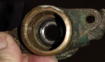
I'm trying to replace all the parts of my Japanese 2gm20 waterpump, and managed to remove everything except the shaft seal. Can anyone tell me if this seal has a metal outside case as it is stuck to the body of the pump with no movement between outside of the seal and pump case?
Have tried soaking and possible drifting from impeller side of pump , but only managed to destroy the rubber lipseal but with no successful movement of the outside case.

Any ideas on its removal please would be gratefully accepted.

Note:
Guide for others maybe doing same job, be very careful drifting bearings off the shaft using socket and hammer, I managed to bend the shaft midway flange, because the socket wasn't deep enough, and the bearings were very tight on the shaft. So now also need a new expensive shaft as well.

Any ideas welcomed

cheers Philip
 
Last edited:
Philip,

The outside of the seal is stiff, but rubber. Can be re enforced but thinking about it I haven't cut one open. They usually come out fairly easily with a pair of needle nose pliers.

The shafts are pretty soft stainless 300 series are by nature that's probably what it's made of.
 
Philip,

The outside of the seal is stiff, but rubber. Can be re enforced but thinking about it I haven't cut one open. They usually come out fairly easily with a pair of needle nose pliers.

The shafts are pretty soft stainless 300 series are by nature that's probably what it's made of.

If your struggling I'm in Plymouth
 
If your struggling I'm in Plymouth


Hi jwfrary thanks for the reply and offer of help. I am actually in Torbay so not that local but thanks anyway.

I will persevere and now I know the case is hard rubber or maybe nylon/plastic, I could maybe burn it out with Blow torch. There seems to be a small recess in the internal casting exactly the size of the seal, then it expands to a larger cavity. this is not allowing me to catch hold of the edge of seal unless I can prise the sides away from the pump body which I don't seem to be able without possible damage to the pump internals.
With the hole on the impeller side of the casting being the same size of the seal I can't drift it from the impeller side either.

I think the blow torch might be the answer?
Will try it and let you know the result.

Cheers Philip

Well I haven never needed to burn one out!

Have you managed it, if not post a picture!
 
Well I haven never needed to burn one out!

Have you managed it, if not post a picture!


Hi again, I tried to burn it out with no success! Having tried several scrapes with different tools I saw what looked to be shiny metal, I found this to be correct. The seal is indeed a metal case rubber seal.
What was also apparent according to a schematic of the pump is, the seal was fitted the wrong way around with the flat outer case butting up to the back of the impeller casing. This would account for why I couldn't drift it out from the impeller side.
I did manage to get it out by using a centre punch between the case and seal but with just one punch at 12, 3, 6, and 9 orientation. I then inserted a file which just happened to be the right internal width of the seal and turned it between the punchings, Success.
Having cleaned the internals am now read for new parts.
What is worrying is the old bearings were so difficult to remove, which is why I damaged the shaft trying to remove them from the WP body, I have checked the internal measurement and found it to be considerably smaller than the 30mm yanmar bearing replacements? Possibly only 29.65mm, is this normal?
If the bearings are mounted on the shaft prior to insertion, I wouldn't be able to get them into the body. If they are fitted separately prior to the shaft being inserted, will the shaft pass through the bearings, as it appears the shaft is the same size of the bearing centre hole?
I don't have the replacement parts yet to try or measure things.

Or do you think I need to get the WP body case milled out to exactly 30mm to accommodate the bearings, so I can pre fit everything to the shaft then insert the whole assembly.

Sorry for the long thread but unsure how best to proceed.

Cheers Philip
 
You shouldnt have to mill anything out if you do you have the wrong bearings!

The lip spring always points toward the fluid.

A large vice should be sufficient to press the bearings onto the shaft and into the housing but you will need various bits of tube to do it successfully.
 
You shouldnt have to mill anything out if you do you have the wrong bearings!

The lip spring always points toward the fluid.

A large vice should be sufficient to press the bearings onto the shaft and into the housing but you will need various bits of tube to do it successfully.


The lip spring always points toward the fluid.

A large vice should be sufficient to press the bearings onto the shaft and into the housing but you will need various bits of tube to do it successfully.
[/QUOTE]


Have ordered all the parts, now just waiting on delivery.

Is it best to press all the bearings onto the shaft first, then install whole lot into the case?
Or press first bearing onto shaft against shaft flange, then install that into the case, followed on with last bearing afterwards? Just wondered if trying to get the whole assembled shaft and two bearings into the case together, might compound the compressing friction between bearings and case and make it more difficult.
 
Bearings go onto the shaft first then into the housing. If you think its really tight then put the housing in the oven for an hour then pop the bearings in. Seal can go on after everything's cooled down.

The yanmar workshop manual which is fairly easy to come by on the internet shows you blown apart diagram of the pump.

Hi again final question.

I have now got all the parts after having to wait while supplier was restocked.

All previous understood thank you for info.

Final question, - on the yanmar schematic for my Japanese 2gm20 , it shows a rubber Flinger washer item no 9 which has to be fitted and which I also have in my new parts. As the shaft has a recess next to the midway flange, does this washer fit against the flange, or the other impeller end just behind the back of the Lipseal? The schematic shows the order to mount parts but not the actual positions.

Thanks again for the help
Philip
 
Top