tudorsailor
Well-known member
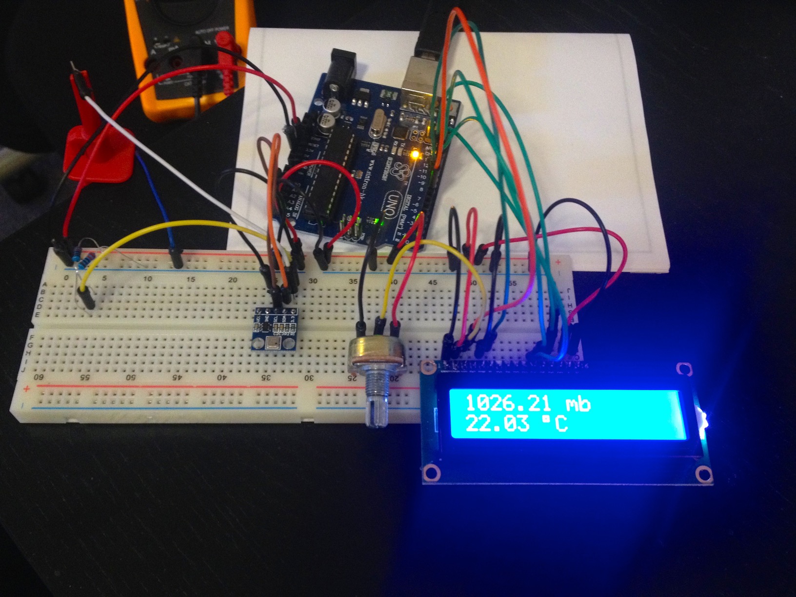
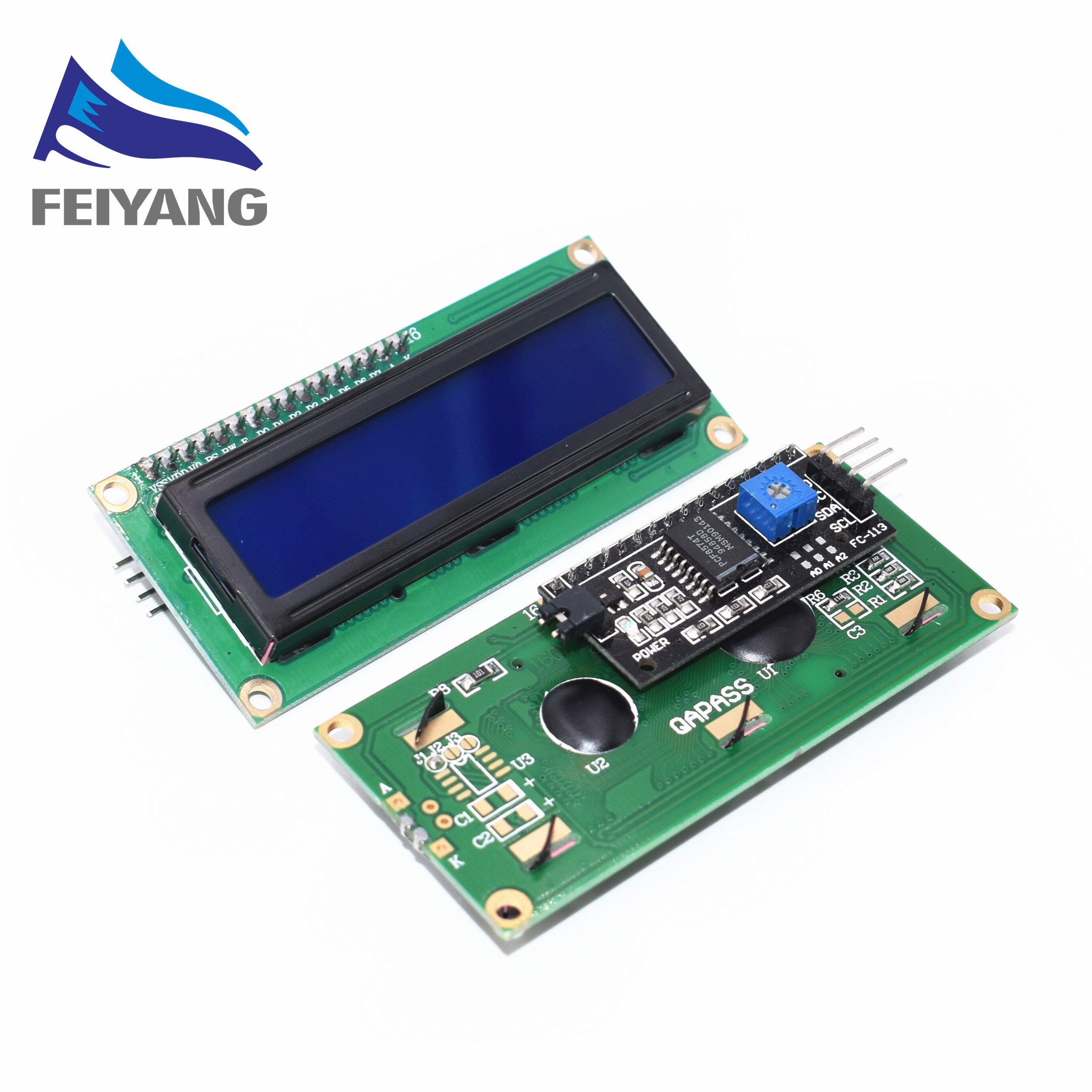
Well the nice man from amazon has delivered the LCD. It has an adapter to allow just 4 pin connection GND VCC SDA and SCL. It is an I2C interface. There are no instructions of course. I assume that I have to solder the adapter onto the LCD. Will the Sketchfrom GHA work with a 4 pin connection? Do I use a breadboard to share the SDA and SCL that are also used by the sensor or is that too simple?


Thanks
Thanks
")