Battery Charging Diode

TernVI

Well-known member
Joined
8 Jul 2020
Messages
5,070
Visit site
Connecting the engine battery to a bank of Trojans, being charged at 14.8v from a 500w solar array will make the engine battery very short lived.

Come to that, the bow battery might not be too happy.

Depending on the batteries being used, a B2B might be a better choice for the bow battery and leave the engine off of solar charging.
Or maybe a diode drop from 14.8V would be about right?
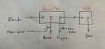
By coincidence the OP has a diode splitter lying idle.
I'm not really keen on just using diodes to drop voltage, because big diodes often have quite small drops at low currents.
Two small B2B chargers would be a proper solution, if the OP thinks he has enough of problem to want to spend three figures solving it.

Personally I think the long lifetimes of the bow and engine batteries suggest the system has some merits as it is.

An electronics DIYer would consider float charging the Bow and Engine batteries from the small solar panel .
Or build a VSR with some intelligence so the over-voltage situations were avoided.
 

Tim Good

Well-known member
Joined
26 Feb 2010
Messages
2,798
Location
Bristol
Visit site
An electronics DIYer would consider float charging the Bow and Engine batteries from the small solar panel .

This is doable since I have a smallpanel on my coach roof in addition to the larger array hanging off the stern. The small panel was just a little addition as I had space and a controller left over. I now have it on a long cable and can move it around at anchor to most effective place. This could go to the engine or bow no problem.
 

PaulRainbow

Well-known member
Joined
16 May 2016
Messages
15,813
Location
Suffolk
Visit site
Engine:
Bosch T4 800a / 140ah. Fully overnight drop tested recently at 58% capacity but the graph shows it’s cranking amps tailing off quite quickly with voltage. Approx 9 years old

Bow:
Optima Yellowtop 975a / 75ah. Fully overnight drop tested recently at 78% capacity. Approx 9 years old.

Another thing to note is that I do have a small 60w panel on the coach roof. It also goes to the house bank. I could leave my main 500w solar bank on the house. Attach the alternator to the bow-battery and then the small solar panel to the engine battery directly. Or small panel to engine and alternator to engine.

The Optima should be OK at the Trojan charging voltages. The engine battery, probably won't be doing it any favours.

So, post #16 is acceptable, with the option of connecting the small panel to the engine battery.

Or, even better:

Leave the large solar array connected to the domestic bank.
Connect the alternator to a Victron ArgoFET with two outputs, one to the engine battery, one to the domestic bank.
Fit a Victron VSR between the engine and bow banks.
Connect the small solar panel to the engine or bow battery.
Mains charger connected to all three banks.
 

Tim Good

Well-known member
Joined
26 Feb 2010
Messages
2,798
Location
Bristol
Visit site
The Optima should be OK at the Trojan charging voltages. The engine battery, probably won't be doing it any favours.

So, post #16 is acceptable, with the option of connecting the small panel to the engine battery.

Or, even better:

Leave the large solar array connected to the domestic bank.
Connect the alternator to a Victron ArgoFET with two outputs, one to the engine battery, one to the domestic bank.
Fit a Victron VSR between the engine and bow banks.
Connect the small solar panel to the engine or bow battery.
Mains charger connected to all three banks.

Excuse my ignorance.. but what is a victron vsr and why not just get a ArgoFET with three posts like my current diode and have the alternator do all three banks?
 

PaulRainbow

Well-known member
Joined
16 May 2016
Messages
15,813
Location
Suffolk
Visit site
Excuse my ignorance.. but what is a victron vsr and why not just get a ArgoFET with three posts like my current diode and have the alternator do all three banks?

VSR = voltage sensing relay.

If you fitted one between the engine and bow batteries it would close and charge both batteries whenever there was a charge going to either battery. So, if the small solar panel was connected to the engine battery, with the VSR it would also charge the bow battery.

You could fit an ArgoFET with 3 outputs, but if you had the VSR you only need to connect the alternator to the engine and domestic banks, the VSR takes care of the bow battery. A 2 output ArgoFET is just over £20 cheaper than a 3 output model, half the cost of a VSR.

For about £160 you can have both devices. The big solar array will charge the Trojans. The small panel will charge the engine and bow batteries. Mains charger will charge all 3, as will the alternator. Job done, all batteries being charged with no user input (y)
 

TernVI

Well-known member
Joined
8 Jul 2020
Messages
5,070
Visit site
VSR = voltage sensing relay.

If you fitted one between the engine and bow batteries it would close and charge both batteries whenever there was a charge going to either battery. So, if the small solar panel was connected to the engine battery, with the VSR it would also charge the bow battery.

You could fit an ArgoFET with 3 outputs, but if you had the VSR you only need to connect the alternator to the engine and domestic banks, the VSR takes care of the bow battery. A 2 output ArgoFET is just over £20 cheaper than a 3 output model, half the cost of a VSR.

For about £160 you can have both devices. The big solar array will charge the Trojans. The small panel will charge the engine and bow batteries. Mains charger will charge all 3, as will the alternator. Job done, all batteries being charged with no user input (y)
And if the sun comes out while you're motoring, your earlier objection to the solar charging the engine battery at 14.8V comes into play?
 

Tim Good

Well-known member
Joined
26 Feb 2010
Messages
2,798
Location
Bristol
Visit site
If you fitted one between the engine and bow batteries it would close and charge both batteries whenever there was a charge going to either battery. So, if the small solar panel was connected to the engine battery, with the VSR it would also charge the bow battery.

Ok so the VSR is really just to the smaller panel can be shared. If I didn’t have a small solar panel then I may as well just have a three stud FET?
 

PaulRainbow

Well-known member
Joined
16 May 2016
Messages
15,813
Location
Suffolk
Visit site
Ok so the VSR is really just to the smaller panel can be shared. If I didn’t have a small solar panel then I may as well just have a three stud FET?

If you just fit the 3 output ArgoFET the only way the engine and bow batteries get charged is when the engine is running.

If you fit the 2 output ArgoFET and the VSR the engine and bow batteries both get charged by the small solar panel.

The cost difference between the two options is about £20, plus a little wire and a fuse. Seems a small price to have all batteries kept charged automagically, but the choice is, of course, yours to make.
 

PaulRainbow

Well-known member
Joined
16 May 2016
Messages
15,813
Location
Suffolk
Visit site
So the argofet switches off? How does it do that? sensing current flow into one output?

The ArgoFET works the same way as a diode, it allows (in my suggested installation) the alternator to charge the engine and domestic banks. The VSR allows the small solar panel to charge both engine and bow batteries. If the VSR is closed because the engine is running there is no path through the ArgoFET for any current to go to the other banks.
 

Tim Good

Well-known member
Joined
26 Feb 2010
Messages
2,798
Location
Bristol
Visit site
If you just fit the 3 output ArgoFET the only way the engine and bow batteries get charged is when the engine is running.

If you fit the 2 output ArgoFET and the VSR the engine and bow batteries both get charged by the small solar panel.

The cost difference between the two options is about £20, plus a little wire and a fuse. Seems a small price to have all batteries kept charged automagically, but the choice is, of course, yours to make.

Makes sense. So like this with the FET and VSR day next to each other? See attachment.

I might add... currently I have a 4 way switch which allows me to bring the batteries together in the case of an emergency. You did actually help me with this on another post but basically the normal setting keeps all banks separate. Another combines house and bow. Another house and engine. And another all three together. This is how I’ve been charging the bow and engine. Messy and not ideal but it’s nice to have the option to bring them together if needed. Presumably this system should still work with the above solution.
 

Attachments

  • F3D1C359-CC61-485E-A5DA-43CCE597FF9F.jpeg
    F3D1C359-CC61-485E-A5DA-43CCE597FF9F.jpeg
    35.7 KB · Views: 14

PaulRainbow

Well-known member
Joined
16 May 2016
Messages
15,813
Location
Suffolk
Visit site
Makes sense. So like this with the FET and VSR day next to each other? See attachment.

I might add... currently I have a 4 way switch which allows me to bring the batteries together in the case of an emergency. You did actually help me with this on another post but basically the normal setting keeps all banks separate. Another combines house and bow. Another house and engine. And another all three together. This is how I’ve been charging the bow and engine. Messy and not ideal but it’s nice to have the option to bring them together if needed. Presumably this system should still work with the above solution.

Your sketch looks right.

That'll take care of everything automagically, your existing emergency switch arrangement will still work if needed, handy if you get a battery fail, for instance.
 

Tim Good

Well-known member
Joined
26 Feb 2010
Messages
2,798
Location
Bristol
Visit site
Your sketch looks right.

That'll take care of everything automagically, your existing emergency switch arrangement will still work if needed, handy if you get a battery fail, for instance.

Ok great thanks. You also mentioned a fuse. Where would that go in the system?
 

PaulRainbow

Well-known member
Joined
16 May 2016
Messages
15,813
Location
Suffolk
Visit site
Ok great thanks. You also mentioned a fuse. Where would that go in the system?

You need to fuse between the VSR and at least one battery to protect the VSR from overload, if the cable run to the other battery might get shorted somehow that should be fused too. You can connect the VSR directly to the batteries or to the battery terminals of the isolator switches, whichever is more convenient.
 
Last edited:

Koeketiene

Well-known member
Joined
24 Sep 2003
Messages
17,756
Location
Finistère
www.sailblogs.com
I have three banks of batteries. But when the engine is on, only the house bank charges.

It’s been like this for a while and it’s been manageable but I’m looming to improve.

Below is a diagram I got from the original owner. It shows a diode with the alternator going to the third prong.

However in reality the alternator goes to the house bank prong. See photo.

I have a couple of questions.

What is this diode meant to do? Share the charge amongst all banks?

At some point the previous owner moved the alternator feed from the middle prong to the house bank prong. Can’t think why but presumably I need to move it back to the middle prong?

Had a similar problem when I bought my current boat.
Only in our case, the engine only charged the starter battery.
So, on day two, I drained/ruined my house battery.

Fitted one of these to solve the problem: Digital Voltage Sensing Relay (DVSR) 12/24V | BEP
 

Tim Good

Well-known member
Joined
26 Feb 2010
Messages
2,798
Location
Bristol
Visit site
You need to fuse between the VSR and at least one battery to protect the VSR from overload, unless the cable run to the other battery might get shorted somehow that should be fused too. You can connect the VSR directly to the batteries or to the battery terminals of the isolator switches, whichever is more convenient.

Hi again Paul,

Would there be any advantages of using two of the VSRs instead of a FET and VSR? Would that allow me to prioritise different banks whereby the FET would just equally distribute charge?

Not sure if possible but you’d wire one vsr like the diagram attached, and then a second attached From the starter pole of the first VSR and then to the bow battery?
 

Attachments

  • 8C7EA6FA-FE06-4CA4-A6C2-3B2D5ED71949.jpeg
    8C7EA6FA-FE06-4CA4-A6C2-3B2D5ED71949.jpeg
    47.8 KB · Views: 3

PaulRainbow

Well-known member
Joined
16 May 2016
Messages
15,813
Location
Suffolk
Visit site
Hi again Paul,

Would there be any advantages of using two of the VSRs instead of a FET and VSR? Would that allow me to prioritise different banks whereby the FET would just equally distribute charge?

Not sure if possible but you’d wire one vsr like the diagram attached, and then a second attached From the starter pole of the first VSR and then to the bow battery?

If you use 2 VSRs all 3 banks will be charged whenever a charging source is present on any bank. This would mean that all the time the Sun is shining your large solar array will be holding the engine and bow batteries at the charging voltage of the Trojans, which would be high for the engine battery. Using the ArgoFET means that the engine and bow battery never get charged by the large array, but they do get charged by the alternator, mains charger and the small solar panel. The domestic bank will get charged by the large solar array, the alternator and the mains charger, as it does now.

The VSRs will not prioritise a bank, despite what some of the manufacturers claim, once the charging voltage on on bank increases to the set point of the VSR the VSR will close and charge the other bank, this will happen in a very short space of time, depending on the state of charge of the "priority" battery.
 

Tim Good

Well-known member
Joined
26 Feb 2010
Messages
2,798
Location
Bristol
Visit site
If you use 2 VSRs all 3 banks will be charged whenever a charging source is present on any bank. This would mean that all the time the Sun is shining your large solar array will be holding the engine and bow batteries at the charging voltage of the Trojans, which would be high for the engine battery. Using the ArgoFET means that the engine and bow battery never get charged by the large array, but they do get charged by the alternator, mains charger and the small solar panel. The domestic bank will get charged by the large solar array, the alternator and the mains charger, as it does now.

The VSRs will not prioritise a bank, despite what some of the manufacturers claim, once the charging voltage on on bank increases to the set point of the VSR the VSR will close and charge the other bank, this will happen in a very short space of time, depending on the state of charge of the "priority" battery.

Ok thanks. Makes total sense..

To add a little complexity into the equation I went to take a closer look at my small solar controller for the small panel. It's a Solara Fox350 and has two outputs. It says:

The FOX-350 is designed for charging 2 separate battery systems. A bistable relay provides the option of switching the charge current to the battery -the batteries are always fully isolated from each other.The relay switches the "+" string, the mass lines of the batteries should be connected with each other.(See connection plan on page 47).The 2-battery logic is only active, if 2 batteries are connected to it. Battery 1 is charged until the charging logic reaches step 3, in order to guarantee that battery 1 is fully charged.In principle, switching-over only becomes active once the battery voltage of battery 2 has fallen below13.8 V.
 
Top