Midnight Drifter
Member
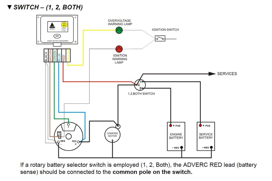
I have an ADVERC battery management unit and want to check that it is correctly connected to my BETA alternator. The ADVERC wiring diagram shows wires going to D+ and DF terminals on the alternator. However, my alternator does not have D+ or DF: its manual shows the following:
B+
L (Ind light)
IG (Excitation)
W (Tacho)
Which of these is equivalent to D+ and DF?
B+
L (Ind light)
IG (Excitation)
W (Tacho)
Which of these is equivalent to D+ and DF?