rolandka
New member
Hi there,
I just want to confirm my thought process with you guys... just to make sure everything is right...
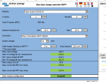
I'm getting 4 x 100W solar panels for now but there will be a possibility to increase the pv array to 600w. So Ideally I want to account for this and get the cable thick enough to handle that load. These panels are 24V and will be charging the 12V LiFePo4 onboard batteries through an MPPT charger (Victron SmartSolar 100/50).
I would like to connect them in parallel so I was wondering what size cable wound I need from the modules to the charger. The modules are roughly about 2-3 meter away from the charger. The battery is no more than 1m away from the battery.
The parameter of the panels:
Power (Pmax): 100 watts
Voltage (Vmp): 36.6V
Max. Current (Imp): 2.81 A
Open circuit voltage (Voc): 42.7 V
Short circuit current (Isc): 3.03 A
Max. System voltage: 1000V
permissible ambient temperature: -40 ° C - + 85 ° C
I want to connect the solars in parallel which means that the amperage is additive. so that means roughly 18amps. I was planning to use 5-8mm2 cables from the pv array to the charger and 16mm2 between the charger and the battery.
Also, I'm thinking to make the parallel connections at the panels but where should I do that really? Should I do it closer to the battery?
Thanks guys!
I just want to confirm my thought process with you guys... just to make sure everything is right...
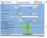
I'm getting 4 x 100W solar panels for now but there will be a possibility to increase the pv array to 600w. So Ideally I want to account for this and get the cable thick enough to handle that load. These panels are 24V and will be charging the 12V LiFePo4 onboard batteries through an MPPT charger (Victron SmartSolar 100/50).
I would like to connect them in parallel so I was wondering what size cable wound I need from the modules to the charger. The modules are roughly about 2-3 meter away from the charger. The battery is no more than 1m away from the battery.
The parameter of the panels:
Power (Pmax): 100 watts
Voltage (Vmp): 36.6V
Max. Current (Imp): 2.81 A
Open circuit voltage (Voc): 42.7 V
Short circuit current (Isc): 3.03 A
Max. System voltage: 1000V
permissible ambient temperature: -40 ° C - + 85 ° C
I want to connect the solars in parallel which means that the amperage is additive. so that means roughly 18amps. I was planning to use 5-8mm2 cables from the pv array to the charger and 16mm2 between the charger and the battery.
Also, I'm thinking to make the parallel connections at the panels but where should I do that really? Should I do it closer to the battery?
Thanks guys!
")