Yet another AC/DC Earthing/Grounding Question

Alex_Blackwood

Well-known member
Joined
19 May 2003
Messages
1,610
Location
Fareham
Visit site
A couple of points Alex.

1) No need to move the GI, it's only there for shore power, would serve no purpose in the generator circuit.

2) There should be an RCD/RCBO in both the shore power and generator circuits, not a shared one after the change over switch, see my comments in post #19
Paul, Take your points. Surly the GI will provide isolation from any stray leakage associated with the boat circuits. I understand the shore power application. I was working on the principle that it won't do any harm if used in both cases. No problem ;)
 

PaulRainbow

Well-known member
Joined
16 May 2016
Messages
15,925
Location
Suffolk
Visit site
Paul, Take your points. Surly the GI will provide isolation from any stray leakage associated with the boat circuits. I understand the shore power application. I was working on the principle that it won't do any harm if used in both cases. No problem ;)
If you look at the OPs drawing you can see that the GI provides protection between all onboard Earths/anodes and the shore power Earth connection, so the generator is in fact covered. (y)
 

stone beach

Member
Joined
27 May 2011
Messages
34
Visit site
Thanks to all for comments so far.
I was unsure about using the Dynaplate for the AC safety earth, I confirm it is underwater and is clean of paint. I understand now this can provide the necessary earth path so I will connect it as mentioned. In fact I thought it was connected thus until I looked very closely the other day, that is what prompted this exercise.
I understand the actions required for RCCB placement, I am about to renew the AC feeder cables from c/o switch to the CU as they are past their prime so I will do all these changes at one go. In the meantime I won't use the generator.
Paul R your #19 :-
"I would note and agree with Tranona regarding the lack of necessity of bonding the through hulls in a GRP boat. I have actually seen where a galvanic problem exists and the through hulls have been degraded to the point they all needed to be changed."
Are you saying that the through hulls in question were degraded because they were included in a bonding arrangement?
In that case I should be removing my bonding "daisy chain" from the through hulls rather than leaving it thinking it can't hurt.
On a new tack, anodes in my engine s.w. cooling systems don't seem to last long, the engines are both connected to the "daisy chain" bonding, if I was to remove that connection the bonding would no longer be connected to battery negative, comments please.
 

PaulRainbow

Well-known member
Joined
16 May 2016
Messages
15,925
Location
Suffolk
Visit site
Thanks to all for comments so far.
I was unsure about using the Dynaplate for the AC safety earth, I confirm it is underwater and is clean of paint. I understand now this can provide the necessary earth path so I will connect it as mentioned. In fact I thought it was connected thus until I looked very closely the other day, that is what prompted this exercise.
I understand the actions required for RCCB placement, I am about to renew the AC feeder cables from c/o switch to the CU as they are past their prime so I will do all these changes at one go. In the meantime I won't use the generator.
Paul R your #19 :-
"I would note and agree with Tranona regarding the lack of necessity of bonding the through hulls in a GRP boat. I have actually seen where a galvanic problem exists and the through hulls have been degraded to the point they all needed to be changed."
Are you saying that the through hulls in question were degraded because they were included in a bonding arrangement?
Yes. Not sure what caused the problems as i wasn't directly involved, but the sail drive was destroyed beyond repair, and the through hulls began to suffer corrosion and had to be replaced.
In that case I should be removing my bonding "daisy chain" from the through hulls rather than leaving it thinking it can't hurt.
If they are not bonded to the anode circuit they cannot be corroded as a result of galvanic issues, they just become independent bits of metal in a plastic hull. I also have a twin engine motorboat and it has 6 bronze through hulls, 2 heads in, 2 heads out and 2 engine seacocks. The heads seacocks are not bonded and are fine, after 35 years. The engine seacocks were replaced just before we bought the boat, 2 years ago, and are bonded. I'll e revising that circuit shortly and removing the bonding from those seacocks.
On a new tack, anodes in my engine s.w. cooling systems don't seem to last long, the engines are both connected to the "daisy chain" bonding, if I was to remove that connection the bonding would no longer be connected to battery negative, comments please.
I'd be cautious here. It's common to connect the bonding circuit to the engine, which in turn creates a circuit to the prop and shaft via the gearbox (with a bridge wire across the coupling if it is of the flexible type). The fact that it creates a connection to the battery negative is incidental and of no concern.
 

Tranona

Well-known member
Joined
10 Nov 2007
Messages
41,002
Visit site
The anodes in the engine cooling system are unconnected with anything outside. They sit in a different body of water/electrolyte. The connection of the anodes to the engine block is quite normal as a path to the shafts. Have you check for continuity from the props to the hull anodes? - this is really the only thing that matters - and are the hull anodes doing anything?

I don't know about the example Paul quotes, but through hulls and valves are often made of plain brass and may dezincify. Bonding to anodes will not stop this. The best metal through hulls and valves are bronze or more recently DZR which is a brass with a small amount of arsenic in the alloy making it "Dezincification Resistant" and effectively as good as the more expensive bronze alloys. As I mentioned earlier the danger with wiring through hulls is that they could be connected to the DC circuits so creating a flow of current that would result in electrolytic action and subsequent corrosion. Very rare, but has been known.

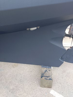
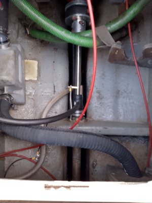
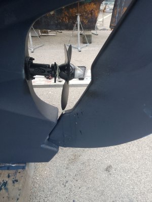
Anodes are sacrificial - that is they introduce a less noble metal into the circuit which will erode in [reference to the less noble metal (usually zinc or aluminium) in the components that need protection. To work they need to be located in the same water and physically close in line of sight. Attaching directly as with prop anodes of on the shaft is best, next best is an anode attached to the hull as close a possible. The photo shows both on my boat - one on the end of the prop and a hull anode as close as we could get it connected to the shaft inside by a spring loaded brush. This requirement for be close in line of sight is another reason why bonding through hulls would not work as on most boats they are not in line of sight.
 

Attachments

  • IMG_20231023_135230.jpg
    IMG_20231023_135230.jpg
    356.1 KB · Views: 3
  • IMG_20231016_165203.jpg
    IMG_20231016_165203.jpg
    277.9 KB · Views: 3
  • IMG_20231023_134639 (1).jpg
    IMG_20231023_134639 (1).jpg
    444.4 KB · Views: 3

Alex_Blackwood

Well-known member
Joined
19 May 2003
Messages
1,610
Location
Fareham
Visit site
If you look at the OPs drawing you can see that the GI provides protection between all onboard Earths/anodes and the shore power Earth connection, so the generator is in fact covered. (y)
I would beg to differ on that Paul. The "Output side of the GI goes to the Earth Connection block as does the generator earth. but that has bypassed the GI. If he connects to his ground plate from the CU earth busbar with the generator in use the GI is out of circuit.
Anyway all a bit academic and is good to have a bit of discussion on it.:unsure:
 

stone beach

Member
Joined
27 May 2011
Messages
34
Visit site
The anodes in the engine cooling system are unconnected with anything outside. They sit in a different body of water/electrolyte. The connection of the anodes to the engine block is quite normal as a path to the shafts. Have you check for continuity from the props to the hull anodes? - this is really the only thing that matters - and are the hull anodes doing anything?

I don't know about the example Paul quotes, but through hulls and valves are often made of plain brass and may dezincify. Bonding to anodes will not stop this. The best metal through hulls and valves are bronze or more recently DZR which is a brass with a small amount of arsenic in the alloy making it "Dezincification Resistant" and effectively as good as the more expensive bronze alloys. As I mentioned earlier the danger with wiring through hulls is that they could be connected to the DC circuits so creating a flow of current that would result in electrolytic action and subsequent corrosion. Very rare, but has been known.

Anodes are sacrificial - that is they introduce a less noble metal into the circuit which will erode in [reference to the less noble metal (usually zinc or aluminium) in the components that need protection. To work they need to be located in the same water and physically close in line of sight. Attaching directly as with prop anodes of on the shaft is best, next best is an anode attached to the hull as close a possible. The photo shows both on my boat - one on the end of the prop and a hull anode as close as we could get it connected to the shaft inside by a spring loaded brush. This requirement for be close in line of sight is another reason why bonding through hulls would not work as on most boats they are not in line of sight.
All understood.
Ref "and are the hull anodes doing anything?" well they are being consumed so I believe they are helping. In my case both shafts have brush gear attached to the "daisy chain" I mentioned.
I understand what actions to take.
 

capblanc

New member
Joined
10 May 2024
Messages
1
Visit site
I am a bit concerned about your AC installation description. Just doesn't seem to be correct. The RCD should be on the output of the rotary switch so that it is in circuit with both shore supply and Generator. Perhaps be better replaced with and RCBO ? You don't say where the AC earth is connected to on the boat. From your description the shore power earth goes to the Galvanic isolator and then to the CU earth bar. Is that Bar connected to earth on the Boat? i.e. an earth plate or stud etc. The Generator earth should also go through the GI.
I won't make any further comment as this could be dangerous without seeing the installation.
Agreed on this. The Gen probably has it's own circuit breaker, if not then there should be on before the selector switch. The shore power should also have its own breaker sized appropriately to the shore cable. This is essential as you have no knowledge of the quality or rating of the protection on shore. After the selector I would recommend a normal RCD rather than an RCBO as it is less whether you have an earth leak or an over current.
Also necessary is a polarity detection system. Again, you will have no knowledge of how well the shore power is connected. Although in the UK it is likely that all is correct, it is possible that a previous boat on the berth has had a problem and has "fiddled" with the wires. If L & N are transposed it means the supposedly neutral bar is now live.
 

PaulRainbow

Well-known member
Joined
16 May 2016
Messages
15,925
Location
Suffolk
Visit site
I would beg to differ on that Paul. The "Output side of the GI goes to the Earth Connection block as does the generator earth. but that has bypassed the GI. If he connects to his ground plate from the CU earth busbar with the generator in use the GI is out of circuit.
Anyway all a bit academic and is good to have a bit of discussion on it.:unsure:
Unfortunately the drawings have vanished Alex. The GI was fitted between the Earth block and the shore power inlet, which is correct, it must be fitted between the shore power Earth and the vessels anode, there can be no other path between the vessels anode and the shore power Earth. The point of the GI is to stop other boats and marina infrastructure from using your anodes, fitted as above this is accomplished.

Can you post a sketch of how you think it should be fitted ?
 

PaulRainbow

Well-known member
Joined
16 May 2016
Messages
15,925
Location
Suffolk
Visit site
Agreed on this. The Gen probably has it's own circuit breaker, if not then there should be on before the selector switch. The shore power should also have its own breaker sized appropriately to the shore cable. This is essential as you have no knowledge of the quality or rating of the protection on shore. After the selector I would recommend a normal RCD rather than an RCBO as it is less whether you have an earth leak or an over current.
This is incorrect, shore power and the generator must both have an RCD before the change over switch.

See posts #19 and #20
 
Top